Mechanical
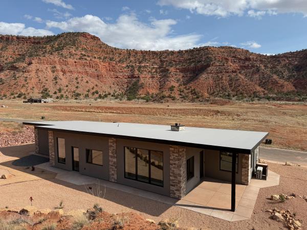
The house is complete! It’s been a busy time, a lot to catch up on. Here’s how it looks today:
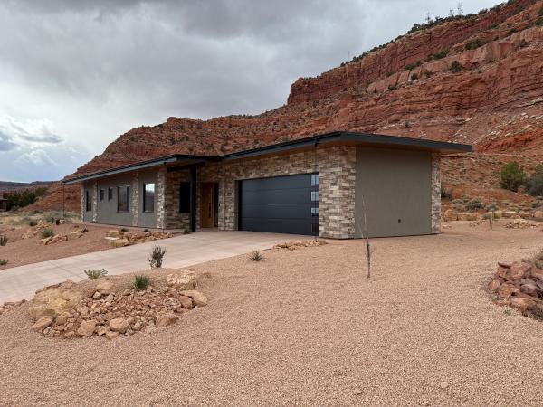
I’ll be posting more pictures soon. But in this post, let’s dive into the guts of the house.
Final blower door test
The preliminary blower door tests came in at 1.6 ACH and 1.1 ACH, not low enough for certification as passive house (0.6) or low energy building (1.0). The builder found and fixed a significant leak after the second test, so we hoped to get a better result at the final blower door test.
Alas, the final test came at 2.2 ACH. And it’s clear that air is coming in from above: most likely, one of the seams in the ceiling membrane has loosened. Major bummer, as that area is now inaccessible.
Changing the air change rate from 0.6 to 2.2 in the PHPP spreadsheet increases heating demand by about 50%, and overall energy consumption goes up about 10%. Still low energy, but not quite as tight as it should be.
Analyzing what went wrong will have to wait for another blog post.
Mechanical
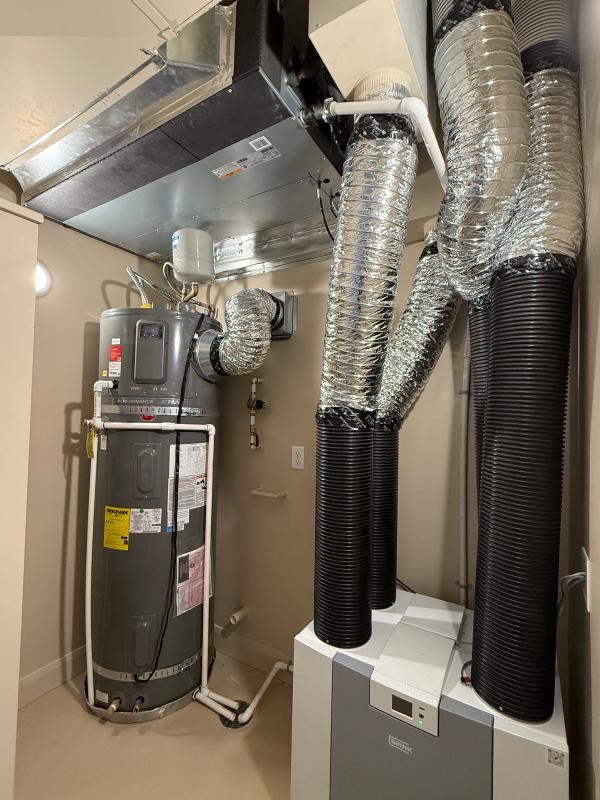
Heating, cooling, ventilation, and water heater were among the last items to be finished. We had decided on a ducted mini-split system for heating and cooling, a Brink Flair 400 ERV for ventilation, and a Rheem ProTerra 80 gallon heat pump water heater.
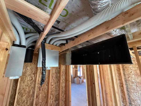
Each one of these is pushing air around, which leads to a lot of ducts. Here you can see the manifolds for the ventilation as well as the big duct that the air handler for the mini-split will push air into.
Here’s a diagram of all the air flows in the house. Green plus is fresh air being supplied to bedrooms and living area; red minus is stale air getting extracted from bathrooms and kitchen area. The mini-split is drawn in purple; blue lines indicate the ducts for warm and cool air. Orange is the cold air exhaust from the heat pump water heater. And gray is my vision for the resulting air flows in the house.
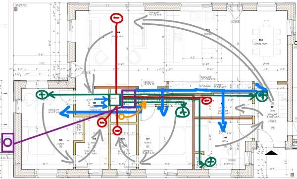
This old sketch is close to reality: the AC guys added some vents into the living area, and also extended one duct to the front door, as shown in the image below.
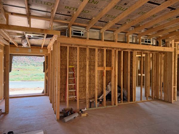
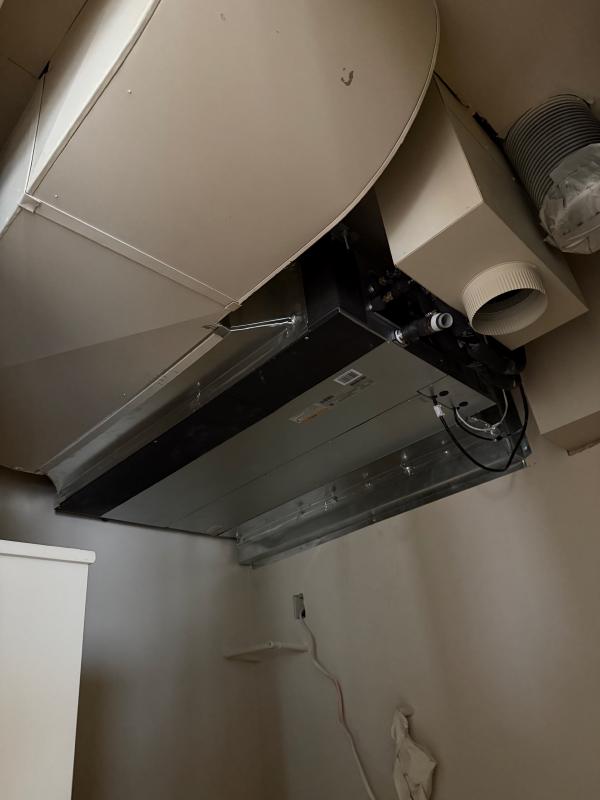
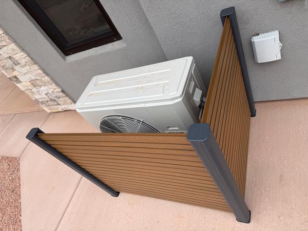
The PHPP spreadsheet told me that a 1-ton mini-split unit would be sufficient to heat and cool the house. (That was assuming we would of course meet the 0.6 ACH goal, so in retrospect that was optimistic.) The AC guys were worried such a small unit would not be able to push enough air, so I reluctantly agreed to let them install a 2-ton system. They ended up installing a 3-ton system. It’s huge, both inside and out.
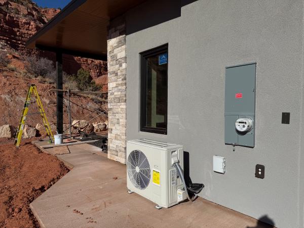
The outside unit is now hidden from view.
Ventilation
As you can see below, arrangement of the ducts bringing in fresh air and venting stale air could have been better. The ducts could also have been shorter if the unit was mounted on the wall instead of placed on the floor, but we didn’t plan for that when building the wall (would need to be stronger).
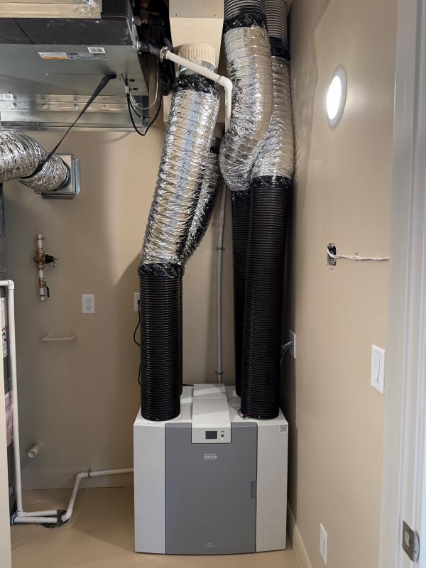
The fresh air intake is under the patio roof.
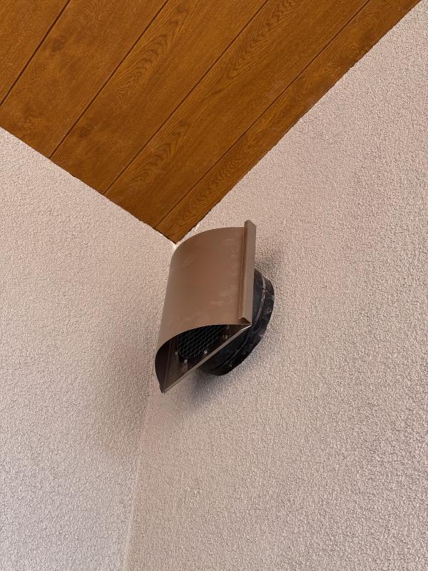
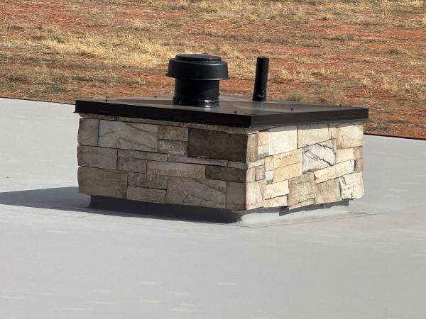
The stale air gets vented through the fake chimney.
The CO2 sensor was an unforeseen complication. I knew the Brink ventilation system came with a CO2 sensor, but I assumed it would be inside the unit, sensing the air as it flowed through. Turns out it’s a separate sensor that needs to be installed in the living area.
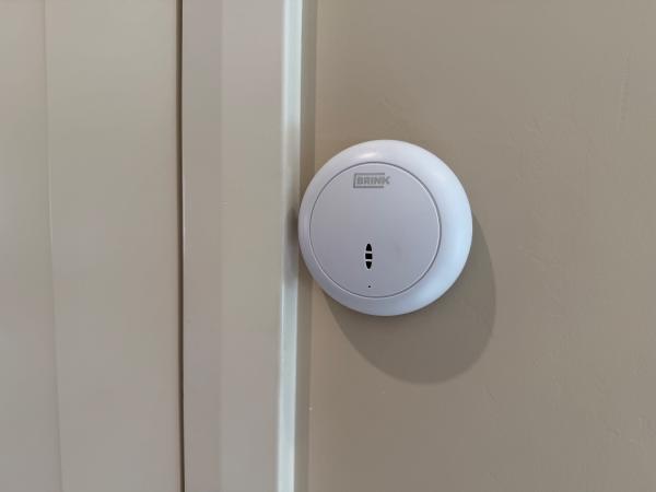
Luckily, we found an unobtrusive place to put it, and the unsightly cables are only visible in the utility room.
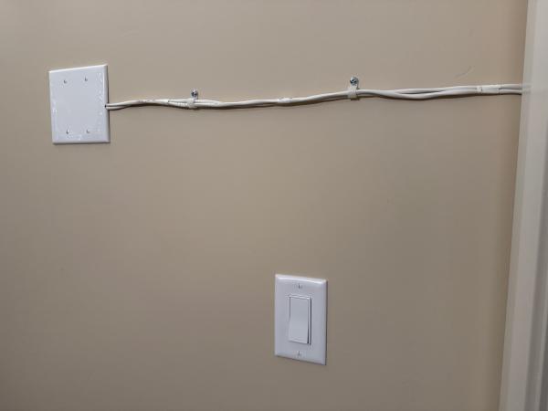
The ventilation automatically increases as the CO2 level goes up.
Sound-dampening measures
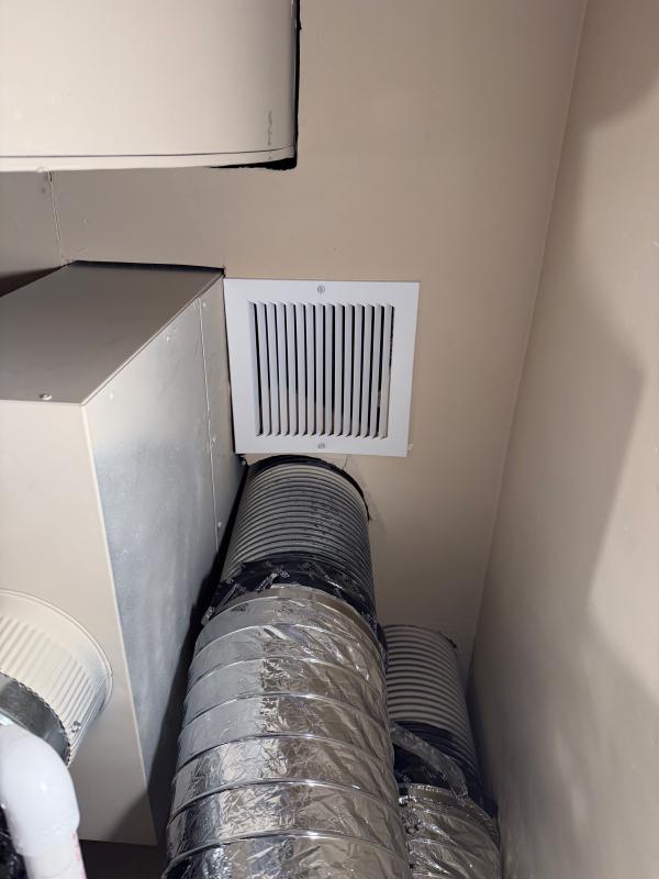
The air handler for the mini-split sits right behind the grille shown below, which meant any noise from the unit came straight out. It was not super-loud, but louder than it should be.
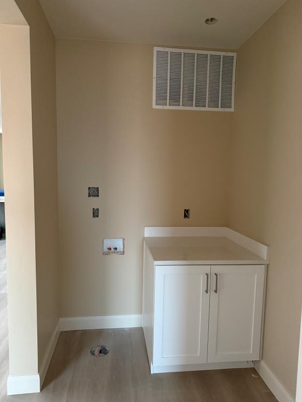
We replaced that grille with a box blocking the direct path of the sound, with added sound-dampening material (made out of old jeans).
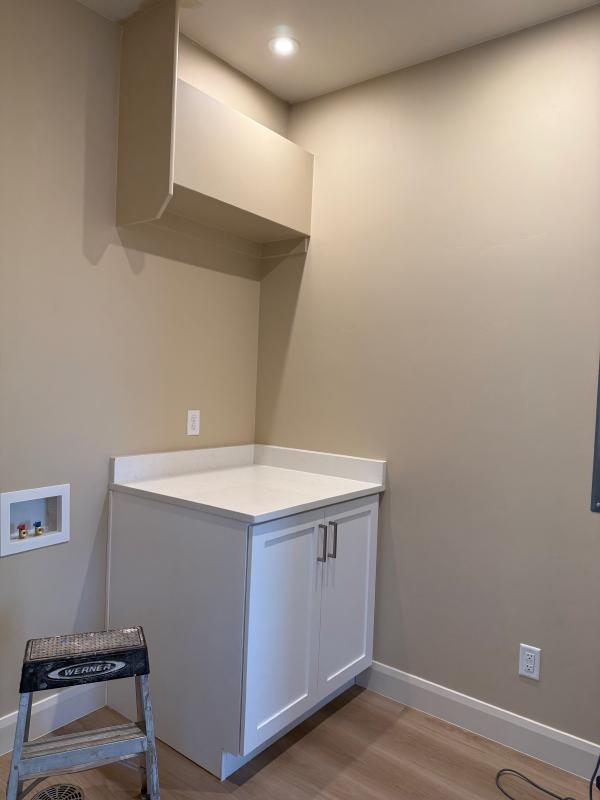
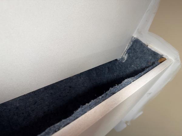
This simple measure significantly reduced the noise, making it a non-issue.
Water heater
The utility room is too small for the water heater to get enough heat from the air in there. For additional air supply, we added a grille in the ceiling so it can draw from all the air in the space between the drop ceiling and the airtight ceiling membrane. (And now we know there’s even more air to draw from there.)
We also need to duct the cold air from the water heater to somewhere outside the room. As shown by the orange arrow in the sketch above, we had planned to take it to the hallway just outside the utility room. However, once we had implemented the sound-dampening box, we decided we could feed that air through a duct in the wall directly into the back of that box.
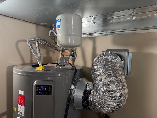
If the heating or cooling is going, that cold air gets sucked directly into the air handler. In summer, this reduces cooling needs; in winter, it needs some extra heating. With this arrangement, we also get additional benefit from the sound dampening.
How is it working?
With the over-dimensioned heating and cooling, changing temperature can be done quickly (the AC guy said he had observed 5 degrees change in 15 minutes). The ventilation works quietly in the background, barely audible when it’s boosted into high gear. And we have not run out of hot water yet.
We’ll see how it works in the heat of summer and cold of winter, but so far, it’s been working well.
